In this second part we’re going to take a more practical approach on how to make your own custom SEGA Master System BIOS.
Bear in mind that the Master System BIOS can only be as big as 32KB so we’ll only be able to fit games which are 32KB in size.
The tools we need are a hex editor and a SMS emulator with a debugger.
The hex editor I use is Hex Fiend which unfortunately is only for macOS but there are probably alternatives for Windows and Linux which are equally capable.
As for the emulator, I use MEKA although it has proven to be pretty inaccurate by modern standards, but it’s very lightweight, cross-platform and the debugger is solid (at least for simple tasks). It’s available for Windows, Linux and macOS.
Make sure to enable the Debugger!
We’ll start with an easy one by making a BIOS with the game TransBot (Astro Flash in Japan) built-in.
Let’s take a peek at the ROM in a hex editor:

…and will you look at that!
The end of the ROM is completely empty, with the exception of the “security header” we don’t care about and can safely ignore.
Looks like the perfect place to put our BIOS in, so let’s do just that.
Let’s grab the 32KB version (for 27c256 EPROM) of the Master System BIOS and copy paste the code at the end of it into our TransBot ROM:
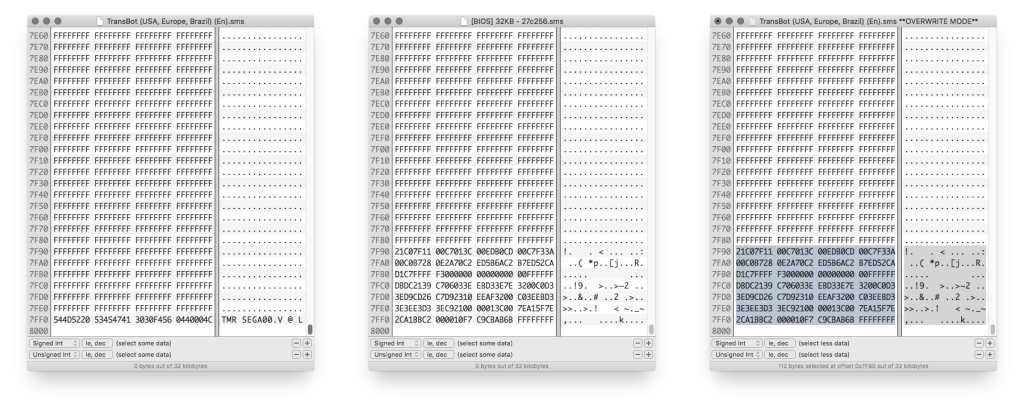
Now let’s take a look at the beginning of the TransBot ROM:

Those are the first 4 bytes we need to move in order to make room for our jump instruction to have the Master System BIOS start first and, if no game is found, start TransBot. Strangely, this doesn’t start with the standard F3 (di) instruction (but if we follow the jump to the address 008A we’ll find one!), so let’s load it into MEKA, enable the debugger and see what’s up.

Interesting! So the game starts right out of the bat with a jump instruction and then a nop (which is an “empty” instruction, it doesn’t do anything, it just waits for one CPU cycle).
We’re in luck! We can just move those 4 bytes to 7FB4 (refer to part 1 of this article) and jump back (which theoretically should not even be needed, but we don’t know how the game is structured so it’s just a safety measure).
Let’s do that:
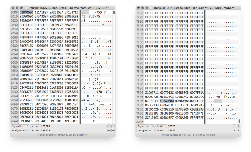
Now we need, as said before as a safety measure, to jump back.
ROM addressing starts at 0000, we took 4 bytes, so we need to jump to 0004 with the instruction jp 0004h which, in bytecode, is C3 04 00.

…and we’re almost done here.
Now all that’s left to do is to put the initial jump at the start of the ROM so that the BIOS routines start first.
We can just copy paste that from the empty 32KB BIOS into our TransBot ROM.
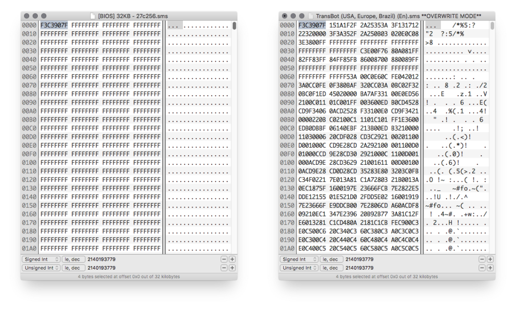
We’re done!
All that’s left to do now is to burn our new custom region-free BIOS with TransBot on a 27c256 EPROM and put it inside our Master System BIOS socket (because you’ve already desoldered the original BIOS and put a socket in, right? 😉 ).
That was pretty easy, let’s now seek for a more serious challenge.
Let’s take a look at an unlicensed Korean game, a port of the famous Gun.Smoke for the SMS!

Ouch.
The game ROM is filled to the brim giving us no space to put the BIOS routines here.
There are two possible approaches here: use a 64KB ROM which is not guaranteed to work on every Master System or… find the space elsewhere.
Let’s take a look around the ROM.

Well well well… look what we got here.
A nice big chunk of empty data right in the middle of the ROM!
Unfortunately we can’t just shift this big part of the ROM to the end because it would break the game (check part 1), but we can definitely shove our BIOS routines in here… with some attention and making small changes.
I’ll take for granted that you’ve read part 1 of this article so you know what I’ll be talking about here (and if you didn’t, now it’s a great time to go back and read it), but the short version of it is that nothing forces us to put the BIOS routines at the end of the ROM. We do that just for convenience because all the various addresses are already set up (and, besides, most of the games leave a lot of empty space at the end).
This time, though, we’ll have to get our hands dirty.
Let’s start by copying the BIOS routines into that empty space.
We’ll put them at address 4F90.
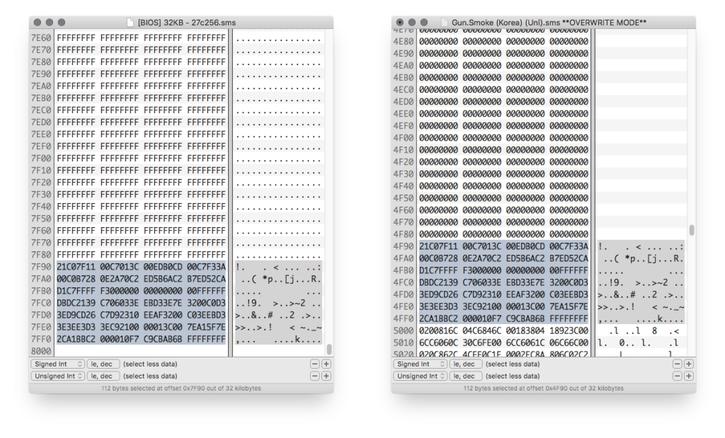
Now we need to remember what this routine does and the important part is the loading of the code into RAM which is right at the beginning.
This is done with 4 instructions:21 C0 7F (ld hl,7FC0h) -> What this says is: the code that needs to be loaded into RAM starts at address 7FC011 00 C7 (ld de,C700h) -> This tells to load the code at RAM address C70001 3C 00 (ld bc,003Ch) -> How many bytes to load into RAM starting from 7FC0. In this case 3C (hexadecimal value!) means 60 bytesED B0 (ldir) -> Load into memory following the previous instructions
Right from the start we can say that the second, third and fourth instruction will remain the same because nothing has changed.
What has changed, though, is the address where the BIOS routine code that gets loaded into RAM actually starts.
Before it was at 7FC0 because it was put at the end of the ROM, but now it is in the middle.
If you look at the previous picture on the left, the one with the “empty” BIOS, you can immediately see the code at 7FC0: it starts with DB DC 21 39 and so on.
Let’s look for that code on the picture on the right and you’ll see that it is now at 4FC0, so we’ll have to change the first instruction from 21 C0 7F (ld hl,7FC0h) to 21 C0 4F (ld hl,4FC0h) so now we have:

One thing down, let’s now take a look at the start of the game:


The game starts with the usual F3 (di) but unfortunately, like in the MDFourier example we made in part 1, it is followed by a 2 byte instruction, ED 56 (im 1). This leaves us 1 byte short which forces us to move the whole following 3 byte instruction C3 3E 01 (jp 013Eh) into our BIOS routine as well.
If you remember what we did in part 1, this is going to be familiar, so I’ll be proceeding a bit faster here.
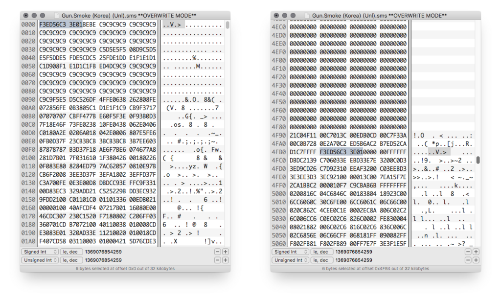
Now we need to add the jump instruction to boot the built-in game in case no cartridge or card game is detected.
Again, to calculate the jump address, remember that we had to move a 1 byte instruction (F3 – di) a 2 byte instruction (ED 56 – im 1) and a 3 byte instruction (C3 3E 01 – jp 013Eh) for a total of 1 + 2 + 3 = 6 bytes.
So our jump will target the address 0006: C3 06 00 (jp 0006h).

Note: just like in our previous example, since the last instruction we moved is a jump, this jump we added should be redundant, but not knowing how the game is structured, it is always best to include it to avoid headaches in the future.
Finally, our last step: replacing the instructions at the beginning of the ROM with our jump to launch the BIOS routines.
We have to be careful though!
Last time the BIOS lived at the end of the ROM, so we could copy-paste the jump instruction from the provided empty 32KB BIOS, but this time the BIOS routines are not at 7F90, but at 4F90, so we have to put in C3 90 4F (jp 4F90h) instead of C3 90 7F (jp 7FC0h).
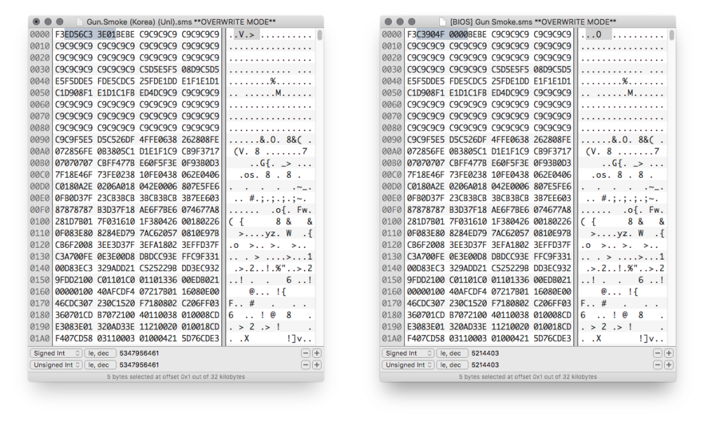
Also, as good practice, make sure to “pad” the rest of those bytes we moved with 00 as shown above.
And we’re done!
This was a bit of tougher one, but hopefully it will have shown you that even if the ROM doesn’t leave you space at the end, you can still manage to squeeze in this small BIOS routine code in empty places even in the middle of the ROM.
There will be a third part of this article more focused on how making a custom BIOS could help diagnose and/or troubleshoot Master System consoles and how I mainly did this for MDFourier, but for now I’ll just leave you with the downloads to “empty” Master System BIOSes that you can use to make your own custom one!
Those are all based on the Japanese v2.1 BIOS which means they’re all region free.
I honestly can’t see the point of making US/EU ones (although it’s possible, as shown in part 1).
Also, please bear in mind that the 64KB one might not work on some Master Systems, but if it works for you it will save you some headaches as you’ll be able to dump in any 32KB game, even ones filled to the end like Gun.Smoke!
Hope you enjoyed the read and happy hacking!

